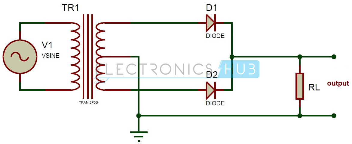
HALF WAVE RECTIFIER
RECTIFIER
A rectifier is an electronic device that
converts AC voltage into DC voltage. It is
done by using a diode or a group of diodes. According
to the period of conduction, rectifiers are classified into two
categories:
1.Half Wave Rectifier
2.Full Wave
Rectifier
In this section,we are going to study Half Wave Rectifier only.
Half wave rectifiers use one diode.
CONCEPT
When a standard AC waveform is
passed through a half-wave rectifier, only half of the AC waveform remains.
Half-wave rectifiers allow only one
half-cycle (positive or negative half-cycle) of the AC voltage through and will
block the other half-cycle on the DC side, as seen below.

Only one P-N junction diode is
required to construct a half-wave rectifier. In essence, this is all that the
half-wave rectifier is doing.
CIRCUIT DIAGRAM

For a sinusoidal input voltage, the no-load
output DC voltage for an ideal half-wave rectifier is
Vrms = Vpeak / 2
Vdc = Vpeak / ᴨ
Where,
·
Vdc, Vav – DC output
voltage or average output voltage
·
Vpeak – Peak value of
input phase voltage
·
Vrms – The output
voltage of root mean square value
WORKING
Case 1
During the positive half cycle, when the
secondary winding of the upper end is positive with respect to the lower end,
the diode is under forwarding bias condition and it conducts current. During
the positive half-cycles, the input voltage is applied directly to the load
resistance. The waveforms of output voltage and output current are the same as
that of the AC input voltage.
Case 2
During the negative half-cycle, when the
secondary winding of the lower end is positive with respect to the upper end,
the diode is under reverse bias condition and it does not conduct current.
During the negative half-cycle, the voltage and current across the load remain
zero. The magnitude of the reverse current is very small and it is neglected.
So, no power is delivered during the negative half cycle.
PEAK INVERSE VOLTAGE
During the negative half cycle when the diode is
reverse biased the maximum value of the voltage coming across the diode is
called the peak inverse voltage. As the current flows through the load resistor
RL, only in one direction, i.e., from M to L. Hence, a DC output is obtained
across RL, which is pulsating in nature.
DISADVANTAGES
- ·
The output is low
because AC supply delivers power only half of the time.
- ·
The output contains more
alternating component (ripples). Therefore, it needs heavy filter circuit to
smooth out the output.
VIDEO ANIMATION

No comments:
Post a Comment